


Scratch Building an SA Dwarf Signal
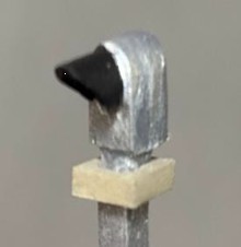
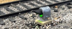
Years ago, I downloaded an article about scratch building an SA dwarf signal. I did not note the source but the instructions used a two lead 3mm bicolor LED. I needed to add dwarf signals to my HO scale layout recently and built a few based on the article, but realized that the 3mm size was a tad too large for my purposes. I decided to use 2 lead 1.8mm bicolor LEDs and altered the plans.
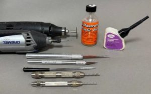
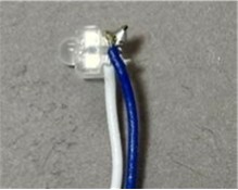
For HO scale I started by cutting a .125 X .125 styrene strip into a 2” long segment to use as the post. I needed to cut a trough down the center of the back to hide the 30 AWG wrapping wires I used. I used a saw attachment to my hobby knife to cut the 1/16” X 1/16” trough down the center length of the back. I needed to hollow out the top back side to house the 1.8 mm led. I used a Dremel tool with a thin sanding disk to rough out the opening being very careful not to go through the sides or go too deep. I squared off the top slot with a Dremel carving/engraving bit and used a tapered file to fine tune. When making the 5/64” lens opening I had to be careful to do it in stages. I started by making an indent about 3/32” from the top end with a small awl to prevent the drill bit from wandering. I first used a 3/64” drill bit in my pin vise then widened using a 5/64” bit. I tested the LED in the slot and filed as needed to make sure the small nub of the LED fit properly through the lens hole. The last step in creating the post was to use a file to round off the top of the post.

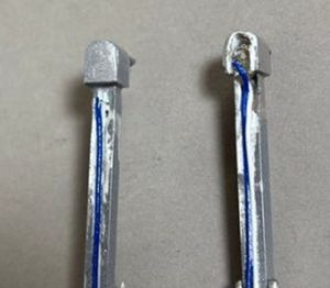
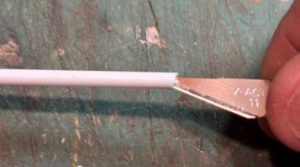
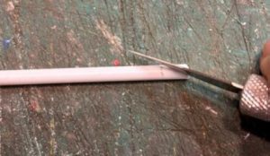
The hood was made by measuring 18 scale inches on a 1/8” styrene tube. I then reamed out the end with a hobby knife to cut down the thickness. Using a hobby knife I cut a diagonal piece starting at the end and angling down to the pencil line. Then cut the tube at the pencil line forming the hood. Depending on the style, you could cut the angle differently to leave part of the rounded tube intact. I glued the hood to the post. Once cured, I fine-tuned the exterior shape of the hood with a file.
To simulate the narrow neck of the post, I filed small, tapered notches on the front and two sides. These notches do not need to be deep; they just need to help define the head.
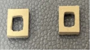
I made a base for the post from .060 X .250 styrene strip. I drew a line every 1/4” for however many I needed. I used an awl to make an indent in the center of each square and used various pin vise drills to increase the size to 1/8”. I finished the base by squaring off the holes with a file, test fitting the post along the way, and cutting into 1/4” squares.
At this stage I spray painted the post and head with grey primer from a rattle can before I added the lens and LED. I wanted to hide the white styrene around the lens opening. Once dry, I used canopy glue to form the lens – follow directions on the container to fill in the hole. Once cured, I placed the LED inside the head making sure the rounded end was aligned with the rounded top of the head. I secured with canopy glue. I made the backside of the head with .020 X .250 styrene, trimming and rounding as needed. I found that I had to slightly grind down the LED nubs and/or slightly hollow out the inside of the back to properly fit. I tested the light before I glued the back!
I finished the signal by using canopy glue to fill in the rear bottom side of the head where the wires descend. Once dried, I used a dark latex paint to cover the head to prevent the light from glowing through. I finished the signal by brush painting the head and top of the post silver and the hood black. The base was painted a concrete color. The base is glued to the post about 1/8” below the head.
Dwarf signals are placed 7’- 6” from the center of the track, usually on the right side and should be slightly angled up to be seen by the engineer.
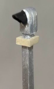
You could easily adapt this design to include double heads to a post.